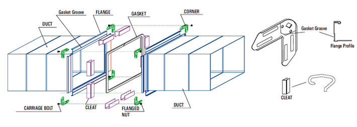
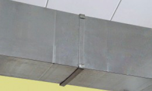
TDF is a flanging system that consists of forming a flange profile on the duct ends, thus made out of a sheet from which the duct is fabricated. TDF is a 4 bolt duct connection system that eliminates time wastage. Rather than using separate connectors to assemble your system, TDF flanges are rollformed onto duct during the manufacturing process. This connection minimizes leakage and installation costs. These TDF flange eliminates the additional internal sealing around the edges of duct & thereby saves the labour & material.
Features :
Highly accurate flange profiles and components ensure ease of fitting and high quality assembly.
A Recessed groove on flange and radial groove on corner pieces for proper gasket seating
Snap fit corner pieces to allow easy fitting at sites
Flexibility to use suit-to-site pieces with ROLAMATE™ slip-on flanges
Slip & Drive Cleats System
Slip and Drive Cleats system is generally used for low-end, less-critical applications. Traditionally, only the Drive cleats ("C") which are positioning cleats were used for all four sides. This was giving a poor joint. The Slip cleats ("S" / "Standing S") on the alternate opposite sides provide the moderate rigidity to the joint.
While installing, Drive cleats are always fitted on the shorter sides and Slip cleats on the longer sides.
Special Notes :
ROLASTAR does not subscribe to usage of red-oxide painted Angle Iron flanges as red-oxide is a known carcinogen.
Conventional G.I. flanges have now become obsolete as they are totally substituted by Slip and Drive cleats system.
TDF can not be made below 250 mm size of the duct. We suggest to use C & S cleat instead of TDF.
ROLASTAR STANDARD
FOR SELECTION OF TDF DUCT GAUGES for 1220 MM coil
Duct Dimension
Duct Pressure in Inches / (Pascals)
1"(250)*
2”(500)**
3”(750)***
4”(1000)
6"(1500)
10”(2500)
in (mm)
TDF (Rolled on flanges)
Rolamate (Slip on flanges)
TDF (Rolled on flanges)
Rolamate (Slip on flanges)
TDF (Rolled on flanges)
Rolamate (Slip on flanges)
TDF (Rolled on flanges)
Rolamate (Slip on flanges)
TDF (Rolled on flanges)
Rolamate (Slip on flanges)
TDF (Rolled on flanges)
Rolamate (Slip on flanges)
200 & Under
26
26 – F
26
26 – F
26
26 – F
26
26 – F
26
26 – F
26
26 – F
200–250
26
26 – F
26
26 – F
26
26 – F
26
26 – F
24
24 – F
24
24 – F
251–300
26
26 – F
26
26 – F
26
26 – F
26
26 – F
24
24 – F
24
24 – F
301–350
26
26 – F
26
26 – F
26
26 – F
26
26 – F
24
24 – F
22
22 – F
351–400
26
26 – F
26
26 – F
26
26 – F
26
26 – F
24
24 – F
20
20 – F
401–450
26
26 – F
26
26 – F
26
26 - F
26
26 – F
24
24 – F
20
20 – F
451–500
26
26 – F
26
26 – F
24
24 – F
24
24 – F
24
24 – F
20
20 – F
501–550
26
26 – F
26
26 – F
24
24 – F
24
24 – F
22
24 – F
20
20 – I
551–600
26
26 – F
26
26 – F
24
24 – F
24
24 – F
22
22 – F
18
20 – I
601–650
26
26 – F
26
26 – F
24
24 – F
22
24 – F
22
22 – F
18
20 – I
651–700
26
26 – F
26
26 – F
24
24 – F
22
24 – F
20
22 – I
18
18 – I
701–750
26
26 – F
24
26 – F
24
24 – F
22
24 – F
20
22 – I
18 – JTR
18 – I
751–900
26
26 – F
24
24 – F
22
22 – F
20
22 – I
18
20 – I
18 – JTR
18 – I
901–1000
24
26 – F
22
24 – F
20
22 – I
18
20 – I
18 – JTR
18 – I
18 – JTR
18 – J
1001–1200
24
24 – F
20
22 – F
20 – JTR
20 – I
18 – JTR
18 – I
18 – JTR
18 – I
16 – JTR
16--J
1201–1300
22
24 – F
20 - JTR
20 – I
18 – JTR
18 – I
18 – JTR
18 – I
16 – JTR
16 – J
16 – JTR
16—J (JTR)
1301–1500
22
24 – F
20 - JTR
20 – I
18 – JTR
18 – I
18 – JTR
18 – I
16 – JTR
16--J
1501–1800
22- JTR
22 – I
20 – JTR
20 – I
18 – JTR
18 – J
16 – JTR
16 – I (JTR)
1801–2100
20- JTR
20 – I
20 – JTR
20-I
16 – JTR
16 – I (JTR)
2101–2400
18- JTR
18 – I
18 – JTR
18 – J
16 – JTR
16-J (JTR)
2401–2700
18- JTR
18 – I
16 – JTR
16 – J (JTR)
2701–3000
16 - JTR
16 - J
Notes :
A higher class flange can always be substituted for a lower class (e.g. Class “J” for Class “H”, / Class “H” for Class “E”, etc.)
1- SMACNA- Sheet Metal and Air conditioning Contractors’ National Association Inc-“HVAC Duct Construction Standards- Metal and Flexible”-2005 (Third Edition), U.S.A. 2- Reading Guide- For duct sizes between, say, 901 mm and 1000 mm, when the pressure class is 1” w.g. static, we require duct gauge of 26 & slip-on connector F. For the same size range but with static pressure at 6” w.g. duct gauge of 18 & slip-on connector I. For the same range in case of TDF flanges in case of pressure class 1” w.g. the gauge should be 24, in case of 6” w.g. the gauge should be 18 g with TDF flange & with joint tie rod (JTR). 3- Use gasket size 10 mm wide and 4.5 mm thick for ducts up to 2” static pressure in case of slip-on flanges upto rigidity class I and for rigidity class above I use 15 mm wide & 6 mm thick gasket. Use gasket size of 15 mm wide X 6 mm thick with pressure class 3” w.g static and above. 4- Cleats should be fixed at max. 150 mm distance from corner & the at the center distance of 250 mm for ducts up to 3” w.g. static. For more than 3” w.g. static the center distance should not exceed 150 mm. 5 (Not applicable to current specification)
For non-critical comfort cooling applications (1” w.g. pressure class), optional “C & S” or “C & SS” cleat joints can be used. Upto 450 mm duct size use “C & S” cleats.
451 to 750 mm duct size use “C & SS” cleats.
Over 750 mm duct size use Rolamate flanges or Rolastar TDF system.
Notes :
* For 1” pressure class we can use cleats.
** Cleats not recommended over 1” pressure class but if it must be used then appropriate sealant is required for all applications above 1” w.g.
*** In any event cleats should not be used for applications over 3” w.g.